There is an introduction to the specification, but reading the OpenGL 2.0 and GLSL official specs is always recommended if you get serious about this. It is assumed that the reader is familiar with OpenGL programming, as this is required to understand some parts of the tutorial.
GLSL stands for GL Shading Language, often referred as glslang, and was defined by the Architectural Review Board of OpenGL, the governing body of OpenGL.
I won't go into disputes, or comparisons, with Cg, Nvidia's proposal for a shading language that is also compatible with OpenGL. The only reason I chose GLSL and not Cg for this tutorial, is GLSL closeness to OpenGL.
Before writing shaders, in any language, it is a good idea to understand the basics of the graphics pipeline. This will provide a context to introduce shaders, what types of shaders are available, and what shaders are supposed to do. It will also show what shaders can't do, which is equally important.
After this introduction the OpenGL setup for GLSL is discussed. The necessary steps to use a shader in an OpenGL application are discussed in some detail. Finally it is shown how an OpenGL application can feed data to a shader making it more flexible and powerful.
Some basic concepts such as data types, variables, statements and function definition are then introduced.
The tutorial covers only the OpenGL 2.0 version (the ARB version has been omitted and is deprecated). OpenGL 2.0 is color coded in orange.
Please bear in mind that this is work in progress and therefore bugs are likely to be present in the text or demos. Let me know if you find any bug, regardless of how insignificant, so that I can clean them up. Also suggestions are more than welcome. I hope you enjoy the tutorial.
Vertex Transformation
In here a vertex is a set of attributes such as its location in space, as well as its color, normal, texture coordinates, amongst others. The inputs for this stage are the individual vertices attributes. Some of the operations performed by the fixed functionality at this stage are:
Primitive Assembly and Rasterization
The inputs for this stage are the transformed vertices, as well as connectivity information. This latter piece of data tells the pipeline how the vertices connect to form a primitive. It is in here that primitives are assembled.
This stage is also responsible for clipping operations against the view frustum, and back face culling.
Rasterization determines the fragments, and pixel positions of the primitive. A fragment in this context is a piece of data that will be used to update a pixel in the frame buffer at a specific location. A fragment contains not only color, but also normals and texture coordinates, amongst other possible attributes, that are used to compute the new pixel's color.
The output of this stage is twofold:
Fragment Texturing and Coloring
Interpolated fragment information is the input of this stage. A color has already been computed in the previous stage through interpolation, and in here it can be combined with a texel (texture element) for example. Texture coordinates have also been interpolated in the previous stage. Fog is also applied at this stage. The common end result of this stage per fragment is a color value and a depth for the fragment.
Raster Operations
The inputs of this stage are:
Visual Summary of the Fixed Functionality
The following figure presents a visual description of the stages presented above:
Replacing Fixed Functionality
Recent graphic cards give the programmer the ability to define the functionality of two of the above described stages:
The following OpenGL code would send to the vertex processor a color and a vertex position for each vertex.
	glBegin(...);

		glColor3f(0.2,0.4,0.6);
		glVertex3f(-1.0,1.0,2.0);

		glColor3f(0.2,0.4,0.8);
		glVertex3f(1.0,-1.0,2.0);

	glEnd();
In a vertex shader you can write code for tasks such as:
As can be seen in the previous subsection the vertex processor has no information regarding connectivity, hence operations that require topological knowledge can't be performed in here. For instance it is not possible for a vertex shader to perform back face culling, since it operates on vertices and not on faces. The vertex processor processes vertices individually and has no clue of the remaining vertices.
The vertex shader is responsible for at least writing a variable: gl_Position, usually transforming the vertex with the modelview and projection matrices.
A vertex processor has access to OpenGL state, so it can perform operations that involve lighting for instance, and use materials. It can also access textures (only available in the newest hardware). There is no access to the frame buffer.
In the vertex shader these values are computed for each vertex. Now we're dealing with the fragments inside the primitives, hence the need for the interpolated values.
As in the vertex processor, when you write a fragment shader it replaces all the fixed functionality. Therefore it is not possible to have a fragment shader texturing the fragment and leave the fog for the fixed functionality. The programmer must code all effects that the application requires.
The fragment processor operates on single fragments, i.e. it has no clue about the neighboring fragments. The shader has access to OpenGL state, similar to the vertex shaders, and therefore it can access for instance the fog color specified in an OpenGL application.
One important point is that a fragment shader can't change the pixel coordinate, as computed previously in the pipeline. Recall that in the vertex processor the modelview and projection matrices can be used to transform the vertex. The viewport comes into play after that but before the fragment processor. The fragment shader has access to the pixels location on screen but it can't change it.
A fragment shader has two output options:
Notice that the fragment shader has no access to the frame buffer. This implies that operations such as blending occur only after the fragment shader has run.
As far as OpenGL goes, setting your application is similar to the workflow of writing a C program. Each shader is like a C module, and it must be compiled separately, as in C. The set of compiled shaders, is then linked into a program, exactly as in C.
To check for OpenGL 2.0 availability you could try something like this
	#include <GL/glew.h>
	#include <GL/glut.h>

	void main(int argc, char **argv) {

		glutInit(&argc, argv);

		...

		glewInit();
		if (glewIsSupported("GL_VERSION_2_0"))
			printf("Ready for OpenGL 2.0\n");
		else {
			printf("OpenGL 2.0 not supported\n");
			exit(1);
		}

		setShaders();

		glutMainLoop();
	}
The figure below shows the necessary steps (in OpenGL 2.0 syntax) to create the shaders, the functions used will be detailed in latter sections.
In the next subsections the steps to create a program are detailed.
The first step is creating an object which will act as a shader container. The function available for this purpose returns a handle for the container.
The OpenGL 2.0 syntax for this function is as follows:
GLuint glCreateShader(GLenum shaderType);
Parameter:
You can create as many shaders as you want to add to a program, but remember that there can only be a main function for the set of vertex shaders and one main function for the set of fragment shaders in each single program.
The following step is to add some source code. The source code for a shader is a string array, although you can use a pointer to a single string.
The syntax of the function to set the source code, in OpenGL 2.0 syntax, for a shader is:
void glShaderSource(GLuint shader, int numOfStrings, const char **strings, int *lenOfStrings);
Parameters:
Finally, the shader must be compiled. The function to achieve this using OpenGL 2.0 is:
void glCompileShader(GLuint shader);
Parameters:
The first step is creating an object which will act as a program container. The function available for this purpose returns a handle for the container.
The syntax for this function, in OpenGL 2.0 syntax is as follows:
GLuint glCreateProgram(void);
You can create as many programs as you want. Once rendering, you can switch from program to program, and even go back to fixed functionality during a single frame. For instance you may want to draw a teapot with refraction and reflection shaders, while having a cube map displayed for background using OpenGL's fixed functionality.
The next step involves attaching the shaders created in the previous subsection to the program you've just created. The shaders do not need to be compiled at this time; they don't even have to have source code. All that is required to attach a shader to a program is the shader container.
To attach a shader to a program use the OpenGL 2.0 function:
void glAttachShader(GLuint program, GLuint shader);
Parameters:
If you have a pair vertex/fragment of shaders you'll need to attach both to the program. You can have many shaders of the same type (vertex or fragment) attached to the same program, just like a C program can have many modules. For each type of shader there can only be one shader with a main function, also as in C.
You can attach a shader to multiple programs, for instance if you plan to use the same vertex shader in several programs.
The final step is to link the program. In order to carry out this step the shaders must be compiled as described in the previous subsection.
The syntax for the link function, in OpenGL 2.0, is as follows:
void glLinkProgram(GLuint program);
Parameters:
After the link operation the shader's source can be modified, and the shaders recompiled without affecting the program.
As shown in the figure above, after linking the program, there is a function to actually load and use the program (OpenGL 2.0) glUseProgram. Each program is assigned an handler, and you can have as many programs linked and ready to use as you want (and your hardware allows).
The syntax for this function is as follows (OpenGL 2.0 notation):
void glUseProgram(GLuint prog);
Parameters:
If a program is in use, and it is linked again, it will automatically be placed in use again, so in this case you don't need to call this function again. I the parameter is zero then the fixed functionality is activated.
OpenGL 2.0 syntax:
	void setShaders() {

		char *vs,*fs;

		v = glCreateShader(GL_VERTEX_SHADER);
		f = glCreateShader(GL_FRAGMENT_SHADER);

		vs = textFileRead("toon.vert");
		fs = textFileRead("toon.frag");

		const char * vv = vs;
		const char * ff = fs;

		glShaderSource(v, 1, &vv,NULL);
		glShaderSource(f, 1, &ff,NULL);

		free(vs);free(fs);

		glCompileShader(v);
		glCompileShader(f);

		p = glCreateProgram();

		glAttachShader(p,v);
		glAttachShader(p,f);

		glLinkProgram(p);
		glUseProgram(p);
	}
A complete GLUT example is available: OpenGL 2.0 syntax, containing two simple shaders, and the text file reading functions.
The status of the compile steps can be queried in OpenGL 2.0 with the following function:
void glGetShaderiv(GLuint object, GLenum type, int *param);
Parameters:
The status of the link step can be queried in OpenGL 2.0 with the following function:
void glGetProgramiv(GLuint object, GLenum type, int *param);
Parameters:
There are more options regarding the second parameter, type, however these won't be explored in here. Check out the 3Dlabs site for the complete specification.
When errors are reported it is possible to get further information with the InfoLog. This log stores information about the last operation performed, such as warnings and errors in the compilation, problems during the link step. The log can even tell you if your shaders will run in software, meaning your hardware does not support some feature you're using, or hardware, the ideal situation. Unfortunately there is no specification for the InfoLog messages, so different drivers/hardware may produce different logs.
In order to get the InfoLog for a particular shader or program in OpenGL 2.0 use the following functions:
void glGetShaderInfoLog(GLuint object, int maxLen, int *len, char *log);
void glGetProgramInfoLog(GLuint object, int maxLen, int *len, char *log);
Parameters:
The GLSL specification could have been nicer in here. You must know the length of the InfoLog to retrieve it. To find this precious bit of information use the following functions (in OpenGL notation):
void glGetShaderiv(GLuint object, GLenum type, int *param);
void glGetProgramiv(GLuint object, GLenum type, int *param);
Parameters:
The following functions can be used to print the contents of the infoLog in OpenGL 2.0:
	void printShaderInfoLog(GLuint obj)
	{
	    int infologLength = 0;
	    int charsWritten  = 0;
	    char *infoLog;

		glGetShaderiv(obj, GL_INFO_LOG_LENGTH,&infologLength);

	    if (infologLength > 0)
	    {
	        infoLog = (char *)malloc(infologLength);
	        glGetShaderInfoLog(obj, infologLength, &charsWritten, infoLog);
			printf("%s\n",infoLog);
	        free(infoLog);
	    }
	}

	void printProgramInfoLog(GLuint obj)
	{
	    int infologLength = 0;
	    int charsWritten  = 0;
	    char *infoLog;

		glGetProgramiv(obj, GL_INFO_LOG_LENGTH,&infologLength);

	    if (infologLength > 0)
	    {
	        infoLog = (char *)malloc(infologLength);
	        glGetProgramInfoLog(obj, infologLength, &charsWritten, infoLog);
			printf("%s\n",infoLog);
	        free(infoLog);
	    }
	}
The OpenGL 2.0 syntax is as follows:
void glDetachShader(GLuint program, GLuint shader);
Parameter:
Only shaders that are not attached can be deleted so this operation is not irrelevant. To delete a shader, or a program, in OpenGL 2.0, use the following functions:
void glDeleteShader(GLuint id);
void glDeleteProgram(GLuint id);
Parameter:
In the case of a shader that is still attached to some (one or more) programs, the shader is not actually deleted, but only marked for deletion. The delete operation will only be concluded when the shader is no longer attached to any program, i.e. it has been detached from all programs it was attached to.
The shader has access to part of the OpenGL state, therefore when an application alters this subset of the OpenGL state it is effectively communicating with the shader. So for instance if an application wants to pass a light color to the shader it can simply alter the OpenGL state as it is normally done with the fixed functionality.
However, using the OpenGL state is not always the most intuitive way of setting values for the shaders to act upon. For instance consider a shader that requires a variable to tell the elapsed time to perform some animation. There is no suitable named variable in the OpenGL state for this purpose. True, you can use an unused lights specular cutoff angle for this but it is highly counterintuitive.
Fortunately, GLSL allows the definition of user defined variables for an OpenGL application to communicate with a shader. Thanks to this simple feature you can have a variable for time keeping appropriately called timeElapsed, or some other suitable name.
In this context, GLSL has two types of variable qualifiers (more qualifiers are available to use inside a shader as detailed in Data Types and Variables subsection):
There is yet another way of sending values to shaders: using textures. A texture doesn't have to represent an image; it can be interpreted as an array of data. In fact, using shaders you're the one who decides how to interpret your textures data, even when it is an image. The usage of textures is not explored in this section since it is out of scope.
The first thing you have to do is to get the memory location of the variable. Note that this information is only available after you link the program. Note: with some drivers you may be required to be using the program, i.e. you'll have to call (openGL 2.0) glUSeProgram before attempting to get the location (it happens with my laptop ATI graphics card).
The function to retrieve the location of an uniform variable given its name, as defined in the shader, is (OpenGL 2.0 syntax):
GLint glGetUniformLocation(GLuint program, const char *name);
Parameters:
The return value is the location of the variable, which can then be used to assign values to it. A family of functions is provided for setting uniform variables, its usage being dependent on the data type of the variable. A set of functions is defined for setting float values as (OpenGL 2.0 notation):
void glUniform1f(GLint location, GLfloat v0);
void glUniform2f(GLint location, GLfloat v0, GLfloat v1);
void glUniform3f(GLint location, GLfloat v0, GLfloat v1, GLfloat v2);
void glUniform4f(GLint location, GLfloat v0, GLfloat v1, GLfloat v2, GLfloat v3);
or
GLint glUniform{1,2,3,4}fv(GLint location, GLsizei count, GLfloat *v);
Parameters:
A similar set of function is available for data type integer, where "f" is replaced by "i". There are no functions specifically for bools, or boolean vectors. Just use the functions available for float or integer and set zero for false, and anything else for true. In case you have an array of uniform variables the vector version should be used.
For sampler variables, use the functions (OpenGL 2.0 notation) glUniform1i, or glUniform1iv if setting an array of samplers.
Matrices are also an available data type in GLSL, and a set of functions is also provided for this data type:
GLint glUniformMatrix{2,3,4}fv(GLint location, GLsizei count, GLboolean transpose, GLfloat *v);
Parameters:
An important note to close this subsection, and before some source code is presented: the values that are set with these functions will keep their values until the program is linked again. Once a new link process is performed all values will be reset to zero.
And now to some source code. Assume that a shader with the following variables is being used:
	uniform float specIntensity;
	uniform vec4 specColor;
	uniform float t[2];
	uniform vec4 colors[3];
In an OpenGL 2.0 application, the code for setting the variables could be:
	GLint loc1,loc2,loc3,loc4;
	float specIntensity = 0.98;
	float sc[4] = {0.8,0.8,0.8,1.0};
	float threshold[2] = {0.5,0.25};
	float colors[12] = {0.4,0.4,0.8,1.0,
				  0.2,0.2,0.4,1.0,
				  0.1,0.1,0.1,1.0};

	loc1 = glGetUniformLocation(p,"specIntensity");
	glUniform1f(loc1,specIntensity);

	loc2 = glGetUniformLocation(p,"specColor");
	glUniform4fv(loc2,1,sc);

	loc3 = glGetUniformLocation(p,"t");
	glUniform1fv(loc3,2,threshold);

	loc4 = glGetUniformLocation(p,"colors");
	glUniform4fv(loc4,3,colors);
A working example, with source code, is available: OpenGL 2.0 syntax.
Notice the difference between setting an array of values, as it is the case of t or colors, and setting a vector with 4 values, as the specColor. The count parameter (middle parameter of glGetUniform{1,2,3,4}fv) specifies the number of array elements as declared in the shader, not as declared in the OpenGL application. So although specColor contains 4 values, the count of the function glUniform4fv parameter is set to 1, because it is only one vector. An alternative for setting the specColor variable could be:
	loc2 = glGetUniformLocation(p,"specColor");
	glUniform4f(loc2,sc[0],sc[1],sc[2],sc[3]);
Yet another possibility provided by GLSL is to get the location of a variable inside an array. For instance, it is possible to get the location of t[1]. The following snippet of code shows this approach to set the t array elements.
	loct0 = glGetUniformLocation(p,"t[0]");
	glUniform1f(loct0,threshold[0]);

	loct1 = glGetUniformLocation(p,"t[1]");
	glUniform1f(loct1,threshold[1]);
Notice how the variable is specified in glGetUniformLocation using the square brackets.
If it is required to set variables per vertex then attribute variables must be used. In fact attribute variables can be updated at any time. Attribute variables can only be read (not written) in a vertex shader. This is because they contain vertex data, hence not applicable directly in a fragment shader (see the section on varying variables). As for uniform variables, first it is necessary to get the location in memory of the variable. Note that the program must be linked previously and some drivers may require that the program is in use.
In OpenGL 2.0 use the following function:
GLint glGetAttribLocation(GLuint program,char *name);
Parameters:
The variable's location in memory is obtained as the return value of the above function. The next step is to specify a value for it, potentially per vertex. As in the uniform variables, there is a function for each data type.
OpenGL 2.0 syntax:
void glVertexAttrib1f(GLint location, GLfloat v0);
void glVertexAttrib2f(GLint location, GLfloat v0, GLfloat v1);
void glVertexAttrib3f(GLint location, GLfloat v0, GLfloat v1,GLfloat v2);
void glVertexAttrib4f(GLint location, GLfloat v0, GLfloat v1,,GLfloat v2, GLfloat v3);
or
GLint glVertexAttrib{1,2,3,4}fv(GLint location, GLfloat *v);
Parameters:
A similar set of functions is provided for integers and some other data types. Note that the vector version is not available for arrays as is the case of uniform variables. The vector version is just an option to submit the values of a single attribute variable. This is similar to what happens in OpenGL with glColor3f and glColor3fv.
A small example is now provided. It is assumed that the vertex shader declare a float attribute named height. The setup phase, to be performed after program link is:
loc = glGetAttribLocation(p,"height");
In the rendering function the code could be something like:
	glBegin(GL_TRIANGLE_STRIP);

		glVertexAttrib1f(loc,2.0);
		glVertex2f(-1,1);

		glVertexAttrib1f(loc,2.0);
		glVertex2f(1,1);

		glVertexAttrib1f(loc,-2.0);
		glVertex2f(-1,-1);

		glVertexAttrib1f(loc,-2.0);
		glVertex2f(1,-1);

	glEnd();
The source code for a small working example is available: OpenGL 2.0 syntax.
Vertex Arrays can also be used together with attribute variables. The first thing to be done is to enable the arrays. To do this for an attribute array use the following function (OpenGL 2.0 syntax):
void glEnableVertexAttribArray(GLint loc);
Parameters:
Next the pointer to the array with the data is provided using the following functions.
OpenGL 2.0 syntax:
void glVertexAttribPointer(GLint loc, GLint size, GLenum type, GLboolean normalized, GLsizei stride, const void *pointer);
Parameters:
And now to some source code. First the initialization step. Two arrays are considered, the vertex and attribute arrays. It is assumed that the variable heights is declared with appropriate scope, i.e. accessible both in here as well as when rendering.
	float vertices[8] = {-1,1, 1,1, -1,-1, 1,-1};
	float heights[4] = {2,2,-2,-2};

	...

	loc = glGetAttribLocation(p,"height");

	glEnableClientState(GL_VERTEX_ARRAY);
	glEnableVertexAttribArrayARB(loc);

	glVertexPointer(2,GL_FLOAT,0,vertices);
	glVertexAttribPointer(loc,1,GL_FLOAT,0,0,heights);
Rendering is exactly the same as before (OpenGL without shaders), just call glDrawArrays for example. A small demo source code is available: OpenGL 2.0 syntax.
Vectors with 2,3 or 4 components are also available for each of the simple data types mentioned above. These are declared as:
Structures are also allowed in GLSL. The syntax is the same as C.
Variables
Declaring a simple variable is pretty much the same as in C, you can even initialize a variable when declaring it.
Matrix selectors can take one or two arguments, for instance m[0], or m[2][3]. In the first case the first column is selected, whereas in the second a single element is selected.
As for structures the names of the elements of the structure can be used as in C, so assuming the structures described above the following line of code could be written:
Variable Qualifiers
Qualifiers give a special meaning to the variable. The following qualifiers are available:
.
The available options are pretty much the same as in C. There are conditional statements, like if-else, iteration statements like for, while and do-while.
A few jumps are also defined:
Functions
As in C a shader is structured in functions. At least each type of shader must have a main function declared with the following syntax:
Data Types and Variables
The following simple data types are available in GLSL:
Float and int behave just like in C, whereas the bool type can take on the values of true or false.
Square matrices 2x2, 3x3 and 4x4 are provided since they are heavily used in graphics. The respective data types are:
A set of special types are available for texture access. These are called samplers and are required to access texture values, also known as texels.
The data types for texture sampling are:
In GLSL, arrays can be declared using the same syntax as in C. However arrays can't be initialized when declared. Accessing array's elements is done as in C.
	struct dirlight {
		vec3 direction;
		vec3 color;
	};
	float a,b;		// two vector (yes, the comments are like in C)
	int c = 2;		// c is initialized with 2
	bool d = true;	// d is true
Declaring the other types of variables follows the same pattern, but there are differences between GLSL and C regarding initialization. GLSL relies heavily on constructor for initialization and type casting.
	float b = 2;		// incorrect, there is no automatic type casting

	float e = (float)2;// incorrect, requires constructors for type casting

	int a = 2;
	float c = float(a); // correct. c is 2.0

	vec3 f;		// declaring f as a vec3
	vec3 g = vec3(1.0,2.0,3.0); // declaring and initializing g
GLSL is pretty flexible when initializing variables using other variables. All that it requires is that you provide the necessary number of components. Look at the following examples.
	vec2 a = vec2(1.0,2.0);
	vec2 b = vec2(3.0,4.0);

	vec4 c = vec4(a,b) // c = vec4(1.0,2.0,3.0,4.0);

	vec2 g = vec2(1.0,2.0);
	float h = 3.0;

	vec3 j = vec3(g,h);
Matrices also follow this pattern. You have a wide variety of constructors for matrices. For instance the following constructors for initializing a matrix are available:
	mat4 m = mat4(1.0) // initializing the diagonal of the matrix with 1.0

	vec2 a = vec2(1.0,2.0);
	vec2 b = vec2(3.0,4.0);

	mat2 n = mat2(a,b); // matrices are assigned in column major order

	mat2 k = mat2(1.0,0.0,1.0,0.0); // all elements are specified
The declaration and initialization of structures is demonstrated below:
	struct dirlight {		// type definition
		vec3 direction;
		vec3 color;
	};

	dirlight d1;
	dirlight d2 = dirlight(vec3(1.0,1.0,0.0),vec3(0.8,0.8,0.4));
In GLSL a few extras are provided to simplify our lives, and make the code a little bit clearer. Accessing a vector can be done using letters as well as standard C selectors.
	vec4 a = vec4(1.0,2.0,3.0,4.0);

	float posX = a.x;
	float posY = a[1];

	vec2 posXY = a.xy;

	float depth = a.w
As shown in the previous code snippet, it is possible to use the letters x,y,z,w to access vectors components. If you're talking about colors then r,g,b,a can be used. For texture coordinates the available selectors are s,t,p,q. Notice that by convention, texture coordinates are often referred as s,t,r,q. However r is already being used as a selector for "red" in RGBA. Hence there was a need to find a different letter, and the lucky one was p.
d1.direction = vec3(1.0,1.0,1.0);
Statements and Functions
Control Flow Statements
	if (bool expression)
		...
	else
		...


	for (initialization; bool expression; loop expression)
		...

	while (bool expression)
		...

	do
		...
	while (bool expression)
Although these are already available in the specification of GLSL, only the if statement is commonly available in current hardware.
The discard keyword can only be used in fragment shaders. It causes the termination of the shader for the current fragment without writing to the frame buffer, or depth.
void main()
User defined functions may be defined. As in C a function may have a return value, and should use the return statement to pass out its result. A function can be void of course. The return type can have any type, but it can't be an array.
The parameters of a function have the following qualifiers available:
A few final notes:
	vec4 toonify(in float intensity) {

		vec4 color;

		if (intensity > 0.98)
			color = vec4(0.8,0.8,0.8,1.0);
		else if (intensity > 0.5)
			color = vec4(0.4,0.4,0.8,1.0);
		else if (intensity > 0.25)
			color = vec4(0.2,0.2,0.4,1.0);
		else
			color = vec4(0.1,0.1,0.1,1.0);

		return(color);
	}
After the vertices, including all the vertex data, are processed they move on to the next stage of the pipeline (which still remains fixed functionality) where connectivity information is available. It is in this stage that the primitives are assembled and fragments computed. For each fragment there is a set of variables that are interpolated automatically and provided to the fragment shader. An example is the color of the fragment. The color that arrives at the fragment shader is the result of the interpolation of the colors of the vertices that make up the primitive.
This type of variables, where the fragment receives interpolated, data are "varying variables". GLSL has some predefined varying variables, such as the above mentioned color. GLSL also allows user defined varying variables. These must be declared in both the vertex and fragment shaders, for instance:
varying float intensity;
A varying variable must be written on a vertex shader, where we compute the value of the variable for each vertex. In the fragment shader the variable, whose value results from an interpolation of the vertex values computed previously, can only be read.
 |
Hello World This pair of vertex/fragment shaders is about the smallest pair we can write. It performs only the standard vertex transformation, and sets the same color for all pixels. It shows several ways of achieving the vertex transformation, and introduces the some of the matrices provided available in GLSL. |
 |
Color Shader A simple example of how to get the color specified in an OpenGL application, using glColor, all the way to the fragment shader. |
 |
Flatten Shader This is a simple example of vertex manipulation. It starts out by flattening a teapot, and it ends up with a vertex shader that animates a wavy teapot, based on a uniform variable to keep track of time. |
 |
Toon Shader In this tutorial it will be shown the impact of placing certain computations on the vertex shader vs. the fragment shader. It uses varying variables to establish communication between shaders, and shows how to access an OpenGL lights position. |
 |
Lighting Shaders Lighting according to the "Mathematics of OpenGL" (chapter of the Red Book) lighting is presented in here. The tutorials starts with a directional light per vertex, i.e. as in OpenGL fixed functionality, and then moves on to per pixel implementations of directional, point and spot lights, all according to the Red Book equations. |
 |
Texturing This tutorial starts from basic texturing, accessing texture coordinates and texels, and moves on to a multitexturing example where one of the texture units is applied to give a glow in the dark effect. |
Vertex Shader
As mentioned before, a vertex shader is responsible for transforming the vertices. In here it will be shown how to transform the vertices following the equations for the fixed functionality.
The fixed functionality states that a vertex is to be transformed by the modelview and projection matrices using the following equation:
vTrans = projection * modelview * incomingVertexIn order to write such a statement in GLSL it is necessary to access the OpenGL state to retrieve both matrices. As mentioned before, part of the OpenGL state is accessible in GLSL, namely the above mentioned matrices. The matrices are provided through predefined uniform variables declared as:
	uniform mat4 gl_ModelViewMatrix;
	uniform mat4 gl_ProjectionMatrix;
One more thing is needed: to access the incoming vertex. These vertices are suplied, one by one, to the vertex shader through a predefined attribute variable:
attribute vec4 gl_Vertex;In order to output the transformed vertex, the shader must write to the also predefined variable gl_Position, declared as a vec4.
Given the above, it is now possible to write a vertex shader that will do nothing more than transform vertices. Note that all other functionality will be lost, meaning, for instance, that lighting computations will not be performed.
The vertex shader has to have a main function. The following code does the trick:
	void main()
	{

		gl_Position = gl_ProjectionMatrix * gl_ModelViewMatrix * gl_Vertex;
	}
In the above code, the projection matrix is multiplied by the modelview matrix for every vertex, which is a clear waste of time since these matrices do not change per vertex. The matrices are uniform variables.
GLSL provides some derived matrices, namely the gl_ModelViewProjectionMatrix that is the result of multiplying the above matrices. So the vertex shader could be written as:
	void main()
	{

		gl_Position = gl_ModelViewProjectionMatrix * gl_Vertex;
	}
The end result is of course the same. Does this guarantee the same transformation as in the fixed functionality? Well in theory yes, but in practice the process of transforming the vertices may not follow the same order as in here. This is normally a highly optimized task in a graphic card, and a special function is provided to take advantage of that optimization. Another reason for this function is due to the limit in the precision of the float data type. When calculus is done in different orders, different results may be obtained due to this limited precision. Hence the GLSL provides a function that guarantees that not only the best performance is obtained but also that the result is always the same as when using the fixed functionality. This magical function is:
vec4 ftransform(void);This function returns the transformed incoming vertex, following the same steps as the fixed functionality does. The shader could then be rewritten as:
	void main()
	{

		gl_Position = ftransform();
	}
Fragment Shader
The fragment shader also has a predefined variable to write the color of the fragment: gl_FragColor. As in the case of vertex shaders, fragment shaders must also have a main function. The following code is for a fragment shader that draws all fragments in a bluish color:
	void main()
	{
		gl_FragColor = vec4(0.4,0.4,0.8,1.0);
	}
The source code for this example can be obtained in here: OpenGL 2.0 syntax.
GLSL has an attribute variable where it keeps track of the current color. It also provides varying variables to get the color from the vertex shader to the fragment shader
	attribute vec4 gl_Color;

	varying vec4 gl_FrontColor; // writable on the vertex shader
	varying vec4 gl_BackColor; // writable on the vertex shader

	varying vec4 gl_Color; // readable on the fragment shader
The idea is as follows:
Enough talk, the code for the vertex shader, where only the front face color is computed is:
void main()
{
	gl_FrontColor = gl_Color;

	gl_Position = ftransform();
}
The fragment shader is also a very simple shader:
void main()
{
	gl_FragColor = gl_Color;
}
First we're going to flatten a 3D model, by setting its z coordinate to zero prior to applying the modelview transformation. The source code for the vertex shader is:
	void main(void)
	{
		vec4 v = vec4(gl_Vertex);
		v.z = 0.0;

		gl_Position = gl_ModelViewProjectionMatrix * v;
	}
First notice that we had to copy the gl_Vertex variable to a local variable. The gl_Vertex is an attribute variable provided by GLSL, and hence it is a read only variable as far as the vertex shader is concerned. Hence to change the values of the incoming vertex coordinates we had to copy it first to the local variable v.
The fragment shader only sets a color, so it's basically the same as the one presented in the Hello World section.
This shader sets the z coordinate of each vertex that is processed to zero. When applied to the teapot, the result is something like the following pictures taken around the flattened teapot:

|

|

|

|
	void main(void)
	{
		vec4 v = vec4(gl_Vertex);
		v.z = sin(5.0*v.x )*0.25;

		gl_Position = gl_ModelViewProjectionMatrix * v;
	}
|
|

|

|

|
The code for the vertex shader becomes something like:
uniform float time;

void main(void)
{
	vec4 v = vec4(gl_Vertex);

	v.z = sin(5.0*v.x + time*0.01)*0.25;

	gl_Position = gl_ModelViewProjectionMatrix * v;
}
As mentioned in the Uniform Variables section, in the OpenGL application two steps are required:
loc = glGetUniformLocation(p,"time");
Where p is the handler to the program, and "time" is the name of the uniform variable as defined in the vertex shader. The variable loc is of type GLint and should be defined in a place where it is also accessible to the render function.
The render function could be something like:
	void renderScene(void) {

		glClear(GL_COLOR_BUFFER_BIT | GL_DEPTH_BUFFER_BIT);

		glLoadIdentity();
		gluLookAt(0.0,0.0,5.0,
			0.0,0.0,0.0,
			0.0f,1.0f,0.0f);

		glUniform1f(loc, time);

		glutSolidTeapot(1);
		time+=0.01;

		glutSwapBuffers();
	}
where the variable time is initialized to some value in the initialization, and is incremented in each frame.
The source code for this last example, together with the shaders can be obtained in here: OpenGL 2.0 syntax.
Note: you'll need to have glew to run this. A Shader Designer project is also available in here. A mpeg showing the effect can be downloaded here. This video was produced using a feature on Shader Designer that creates an AVI movie, and afterwards it was converted to MPEG using Fx Mpeg Writer Free version.
So if we have a normal that is close to the light's direction, then we'll use the brightest tone. As the angle between the normal and the light's direction increases darker tones will be used. In other words, the cosine of the angle provides an intensity for the tone.
In this tutorial we'll start with a version that computes the intensity per vertex. Then we will move this computation to the fragment shader. It will also be shown how to access OpenGL light's position.
The first version presented in here computes an intensity per vertex. Then the fragment shader uses the vertex interpolated intensity to compute a tone for the fragment. The vertex shader must therefore declare a varying variable to store the intensity. The fragment shader must declare the same variable, also using the varying qualifier, to receive the properly interpolated value for the intensity.
The light direction could be defined in the vertex shader as a local variable or as a constant, however having it as a uniform variable provides more freedom since it can be set arbitrarily on the OpenGL application. The light's direction variable will be defined in the shader as
For now, lets assume that the light's direction is defined in world space.
The vertex shader has access to the normals, as specified in the OpenGL application, through the attribute variable gl_Normal. This is the normal as defined in the OpenGL application with the glNormal function, hence in model local space.
If no rotations or scales are performed on the model in the OpenGL application, then the normal defined in world space, provided to the vertex shader as gl_Normal, coincides with the normal defined in the local space. The normal is a direction and therefore it is not affected by translations.
Because both the normal and the light's direction are specified in the same space, the vertex shader can jump directly to the cosine computation between the light's direction, i.e. lightDir, and the normal. The cosine can be computed using the following formula
Therefore the cosine, which we will store in a variable named intensity, can be computed with the dot function provided by GLSL.
The only thing that's left to do in the vertex shader is to transform the vertex coordinates. The complete code for the shader is as follows:
Now, in the fragment shader, all that's left to do is to define a color for the fragment based on the intensity. The intensity must be passed on to the fragment shader, since it is the fragment shader that is responsible for setting the colors for fragments. As mentioned before, the intensity will be defined as a varying variable on both shaders, hence it must be written in the vertex shader for the fragment shader to read it.
The color can be computed in the fragment shader as follows:
As can be seen from the code above, the brightest color is used when the cosine is larger than 0.95 and the darker color is used for cosines smaller than 0.25.
All there is left to do in the fragment shader is to set the gl_FragColor based on the color. The code for the fragment shader is:
The following image shows the end result, and it doesn't look very nice does it? The main problem is that we're interpolating the intensity. This is not the same as computing the intensity with the proper normal for the fragment. Go on to the next section to see toon shading done properly!
GLSL has an attribute variable where it keeps track of the current color.
In this section we will do the toon shader effect per fragment. In order to do that, we need to have access to the fragments normal per fragment. Hence the vertex shader only needs to write the normal into a varying variable, so that the fragment shader has access to the interpolated normal.
The vertex shader gets simplified, since the color intensity computation will now be done in the fragment shader. The uniform variable lightDir also has moved to the fragment shader, since it is no longer used in the vertex shader. See the code bellow for the new vertex shader:
In the fragment shader we now need to declare the uniform variable lightDir since the intensity is based on this variable. A varying variable is also defined to receive the interpolated normal. The code for the fragment shader then becomes:
And the result is:
Toon Shading
Toon shading is probably the simplest non-photorealistic shader we can write. It uses very few colors, usually tones, hence it changes abruptly from tone to tone, yet it provides a sense of 3D to the model. The following image shows what we're trying to achieve.

Toon Shading - Version I
uniform vec3 lightDir;
cos(lightDir,normal) = lightDir . normal / ( |lightDir| * |normal| )
where "." is the inner product, aka as the dot product. This can be simplified if both the normal and lightDir are normalized, i.e.
	| normal | = 1
	| lightDir | = 1
Hence if these two conditions are guaranteed the computation for the cosine can be simplified to
cos(lightDir,normal) = lightDir . normal
Since the variable lightDir is supplied by the OpenGL application we can assume that it arrives at the shader already normalized. It would be a waste of time having to normalize it for every vertex, instead of performing it only when the lightDir changes. Also it is reasonable to expect that the normals from the OpenGL application are normalized.
intensity = dot(lightDir, gl_Normal);
	uniform vec3 lightDir;

	varying float intensity;

	void main()
	{
		vec3 ld;

		intensity = dot(lightDir,gl_Normal);

		gl_Position = ftransform();
	}
	vec4 color;

	if (intensity > 0.95)
		color = vec4(1.0,0.5,0.5,1.0);
	else if (intensity > 0.5)
		color = vec4(0.6,0.3,0.3,1.0);
	else if (intensity > 0.25)
		color = vec4(0.4,0.2,0.2,1.0);
	else
		color = vec4(0.2,0.1,0.1,1.0);
	varying float intensity;

	void main()
	{
		vec4 color;

		if (intensity > 0.95)
			color = vec4(1.0,0.5,0.5,1.0);
		else if (intensity > 0.5)
			color = vec4(0.6,0.3,0.3,1.0);
		else if (intensity > 0.25)
			color = vec4(0.4,0.2,0.2,1.0);
		else
			color = vec4(0.2,0.1,0.1,1.0);

		gl_FragColor = color;
	}

Toon Shader - Version II
GLSL has access to part of the OpenGL state. In this tutorial we'll see how to access the color as set in an OpenGL application with glColor.
	varying vec3 normal;

	void main()
	{
		normal = gl_Normal;

		gl_Position = ftransform();
	}
	uniform vec3 lightDir;

	varying vec3 normal;

	void main()
	{

		float intensity;
		vec4 color;

		intensity = dot(lightDir,normal);

		if (intensity > 0.95)
			color = vec4(1.0,0.5,0.5,1.0);
		else if (intensity > 0.5)
			color = vec4(0.6,0.3,0.3,1.0);
		else if (intensity > 0.25)
			color = vec4(0.4,0.2,0.2,1.0);
		else
			color = vec4(0.2,0.1,0.1,1.0);

		gl_FragColor = color;
	}
Let's look closely at the differences between the two versions. In the first version we computed an intensity in the vertex shader and used the interpolated value in the fragment shader. In the second version we interpolated the normal, in the vertex shader, for the fragment shader where we computed the dot product. Interpolation and dot product are both linear operations, so it doesn't matter if we compute the dot product first and then interpolate, or if we interpolate first and then compute the dot product.
What is wrong in here is the usage of the interpolated normal for the dot product in the fragment shader! And it is wrong because the normal, although it has the right direction, it most likely has a not unit length.
We know that the direction is right because we assumed that the normals that arrived at the vertex shader were normalized, and interpolating normalized vectors, provides a vector with the correct direction. However the length is wrong in the general case because interpolating normalized normals only yields a unit length vector if the normals being interpolated have the same direction, which is highly unlikely in smooth surfaces. See Normalization Issues for more details.
The main reason to move the intensity computation from the vertex shader to the fragment shader was to compute it using the proper normal for the fragment. We have a normal vector that has the correct direction but is not unit length. In order to fix this all we have to do is to normalize the incoming normal vector at the fragment shader. The following code is the correct and complete toon shader:
	uniform vec3 lightDir;

	varying vec3 normal;

	void main()
	{

		float intensity;
		vec4 color;


		intensity = dot(lightDir,normalize(normal));

		if (intensity > 0.95)
			color = vec4(1.0,0.5,0.5,1.0);
		else if (intensity > 0.5)
			color = vec4(0.6,0.3,0.3,1.0);
		else if (intensity > 0.25)
			color = vec4(0.4,0.2,0.2,1.0);
		else
			color = vec4(0.2,0.1,0.1,1.0);

		gl_FragColor = color;
	}
The result for this version of the toon shader is depicted below. It looks nicer, yet it is not perfect. It suffers from aliasing, but this is outside the scope of this tutorial ;)
We shall assume that the first light (GL_LIGHT0) in the OpenGL application is a directional light.
GLSL provides access to part of the OpenGL state, namely the lights properties. GLSL declares a C type struct for the lights properties, and an array to store these properties for each of the lights.
struct gl_LightSourceParameters {
	vec4 ambient;
	vec4 diffuse;
	vec4 specular;
	vec4 position;
	...
};

uniform gl_LightSourceParameters gl_LightSource[gl_MaxLights];
This means that we can access the light's direction (using the position field of a directional light) in the vertex shader. Again we shall assume that the light's direction is normalized by the OpenGL application.
The OpenGL specification states that when a light position is set it is automatically converted to eye space coordinates, i.e. camera coordinates. We can assume that the light position stays normalized when automatically converted to eye space. This will be true if we the upper left 3x3 sub matrix of the modelview matrix is orthogonal (this is ensured if we set the camera using gluLookAt, and we don't use scales in our application).
We have to convert the normal to eye space coordinates as well to compute the dot product, as it only makes sense to compute angles, or cosines in this case, between vectors in the same space, and as mentioned before the light position is stored in eye coordinates.
To transform the normal to eye space we will use the pre-defined uniform variable mat3 gl_NormalMatrix. This matrix is the transpose of the inverse of the 3x3 upper left sub matrix from the modelview matrix. We will do the normal transformation per vertex. The vertex shader then becomes:
	varying vec3 normal;

	void main()
	{

		normal = gl_NormalMatrix * gl_Normal;

		gl_Position = ftransform();
	}
In the fragment shader we must access the light position to compute the intensity:
	varying vec3 normal;

	void main()
	{
		float intensity;
		vec4 color;
		vec3 n = normalize(normal);

		intensity = dot(vec3(gl_LightSource[0].position),n);

		if (intensity > 0.95)
			color = vec4(1.0,0.5,0.5,1.0);
		else if (intensity > 0.5)
			color = vec4(0.6,0.3,0.3,1.0);
		else if (intensity > 0.25)
			color = vec4(0.4,0.2,0.2,1.0);
		else
			color = vec4(0.2,0.1,0.1,1.0);

		gl_FragColor = color;
	}
Source code based no GLUT and GLEW is available in here: OpenGL 2.0 syntax.
We'll build the shader incrementally starting with ambient light up to specular lighting.
 |
 |
 |
| Ambient | Ambient + Diffuse | Specular |
Then we'll move on to lighting per pixel in order to get better results.
Next we'll implement point and spot lights per pixel. These last tutorials are heavily based on the directional lights tutorial because most of the code is common.
|
 |
| Point Light | Spot Light |
As mentioned in the toon shader tutorial GLSL offers access to the OpenGL state that contains data for the light setting. This data describes the individual light's setting as well as global parameters.
	struct gl_LightSourceParameters {
		vec4 ambient;
		vec4 diffuse;
		vec4 specular;
		vec4 position;
		vec4 halfVector;
		vec3 spotDirection;
		float spotExponent;
		float spotCutoff; // (range: [0.0,90.0], 180.0)
		float spotCosCutoff; // (range: [1.0,0.0],-1.0)
		float constantAttenuation;
		float linearAttenuation;
		float quadraticAttenuation;
	};

	uniform gl_LightSourceParameters gl_LightSource[gl_MaxLights];

	struct gl_LightModelParameters {
		vec4 ambient;
	};

	uniform gl_LightModelParameters gl_LightModel;
Material properties are accessible in GLSL as well:
	struct gl_MaterialParameters {
		vec4 emission;
		vec4 ambient;
		vec4 diffuse;
		vec4 specular;
		float shininess;
	};

	uniform gl_MaterialParameters gl_FrontMaterial;
	uniform gl_MaterialParameters gl_BackMaterial;
Most of these parameters, both for lighting and materials are familiar to those used to build applications in OpenGL. We shall use these properties to implement our directional light.
We'll start with the diffuse term. The diffuse lighting in OpenGL assumes that the light is perceived with the same intensity regardless if the viewers position. Its intensity is proportional to both the lights diffuse intensity as well as material's diffuse reflection coefficient. The intensity is also proportional to the angle between the light direction and the normal of the surface.
where I is the reflected intensity, Ld is the light's diffuse color (gl_LightSource[0].diffuse), and Md is the material's diffuse coefficient (gl_FrontMaterial.diffuse).
This is known as Lambertian Reflection. 'Lambert's cosine law' states that the brightness of a diffusely radiating plane surface is proportional to the cosine of the angle formed by the line of sight and the normal to the surface. This was more than 200 years ago (Johann Heinrich Lambert, 1728-1777)!
The vertex shader to implement this formula will use the lights properties, namely its position, and diffuse intensity. It will also use the materials diffuse setting. Hence to use this shader just set the light as usual in OpenGL. Note however that since we're not using the fixed functionality, there is no need to enable the lights.
Since we need to compute a cosine, first we're going to make sure that the normal vector and the light direction vector (gl_LightSource[0].position) are normalized, and then we'll use the dot product to get the cosine. Note that, for directional lights, OpenGL stores the light direction as the vector from the vertex to the light source, which is the opposite to what is shown in the above figure.
OpenGL stores the lights direction in eye space coordinates; hence we need to transform the normal to eye space in order to compute the dot product. To transform the normal to eye space we will use the pre-defined uniform variable mat3 gl_NormalMatrix. This matrix is the transpose of the inverse of the 3x3 upper left sub matrix from the modelview matrix.
The following vertex shader shows the GLSL code to achieve this.
	void main() {

		vec3 normal, lightDir;
		vec4 diffuse;
		float NdotL;

		/* first transform the normal into eye space and normalize the result */
		normal = normalize(gl_NormalMatrix * gl_Normal);

		/* now normalize the light's direction. Note that according to the
		OpenGL specification, the light is stored in eye space. Also since
		we're talking about a directional light, the position field is actually
		direction */
		lightDir = normalize(vec3(gl_LightSource[0].position));

		/* compute the cos of the angle between the normal and lights direction.
		The light is directional so the direction is constant for every vertex.
		Since these two are normalized the cosine is the dot product. We also
		need to clamp the result to the [0,1] range. */
		NdotL = max(dot(normal, lightDir), 0.0);

		/* Compute the diffuse term */
		diffuse = gl_FrontMaterial.diffuse * gl_LightSource[0].diffuse;

		gl_FrontColor =  NdotL * diffuse;

		gl_Position = ftransform();
	}
Now in the fragment shader all there is left to do is setting the fragments color, using the varying gl_Color variable.
	void main()
	{
		gl_FragColor = gl_Color;
	}
The following image shows this shader applied to the teapot. Note that the bottom of the teapot is too dark. This is because we're not taking into account the ambient lighting terms available in OpenGL.
Incorporating the ambient terms is also easy to do. There is a global ambient term and a light ambient term. The formula for the ambient term is as follows:
The vertex shader needs to add a few instructions to compute the ambient term:
	void main()
	{
		vec3 normal, lightDir;
		vec4 diffuse, ambient, globalAmbient;
		float NdotL;

		normal = normalize(gl_NormalMatrix * gl_Normal);
		lightDir = normalize(vec3(gl_LightSource[0].position));
		NdotL = max(dot(normal, lightDir), 0.0);
		diffuse = gl_FrontMaterial.diffuse * gl_LightSource[0].diffuse;

		/* Compute the ambient and globalAmbient terms */
		ambient = gl_FrontMaterial.ambient * gl_LightSource[0].ambient;
		globalAmbient = gl_LightModel.ambient * gl_FrontMaterial.ambient;

		gl_FrontColor =  NdotL * diffuse + globalAmbient + ambient;

		gl_Position = ftransform();
	}
The following image shows the end result. Adding an ambient term washes out color, but it's a cheap workaround for the lack of a global illumination model where light bounces, and hence it affects surfaces not directly affected by the light source.
Move on to the next section for the specular component.
The Phong model says that the specular component is proportional to the cosine between the light reflection vector and the eye vector. The following image shows this graphically:
L is the vector from the light to the vertex being shaded. N is the normal vector, and Eye is the vector from the vertex to the eye, or camera. R is the vector L mirror reflected on the surface. The specular component is proportional to the cosine of alpha.
If the eye vector coincides with the reflection vector then we get the maximum specular intensity. As the eye vector diverges from the reflection vector the specular intensity decays. The rate of decay is controlled by a shininess factor. The higher the shininess factor the faster the decay. This means that with a high shininess the bright spot caused by the specular component is smaller than with a low shininess value. Simply put, the shininess (a value between 0 and 128 in OpenGL) controls the size of the bright spot.
 |
 |
 |
| Shininess = 8 | Shininess = 64 | Shininess = 128 |
The formula for the reflection vector is as follows:
And the specular component in OpenGL using the Phong model would be:
Where the s exponent is the shininess value, Ls is the lights specular intensity, and Ms is the materials specular coefficient.
Blinn proposed a simpler and faster model, knows as the Blinn-Phong model that is based on the half-vector. The half-vector is a vector with a direction half-way between the eye vector and the light vector as shown in the following figure:
The intensity of the specular component is now based on the cosine of the angle between the half vector and the normal. The formula for the half-vector is much simpler than for the reflection vector:
And the specular component in OpenGL using the Blinn-Phong model is:
This is the actual stuff as commonly used in the fixed pipeline of the graphics hardware. Since we want to emulate the OpenGL's directional light, we're going to use this last equation in our shader. There is a good news: OpenGL computes the half-vector for us! So the following snippet of code should do the trick:
	/* compute the specular term if NdotL is  larger than zero */
	if (NdotL > 0.0) {

		// normalize the half-vector, and then compute the
		// cosine (dot product) with the normal
		NdotHV = max(dot(normal, gl_LightSource[0].halfVector.xyz),0.0);
		specular = gl_FrontMaterial.specular * gl_LightSource[0].specular *
				pow(NdotHV,gl_FrontMaterial.shininess);
	}
The full source of the shaders, in a Shader Designer project can be found in here.
First lets take a look at the information we receive per vertex:
We can also perform some computations combining the lights settings with the materials in the vertex shader, hence helping to split the load between the vertex and fragment shader.
The vertex shader could be:
	varying vec4 diffuse,ambient;
	varying vec3 normal,lightDir,halfVector;

	void main()
	{
		/* first transform the normal into eye space and
		normalize the result */
		normal = normalize(gl_NormalMatrix * gl_Normal);

		/* now normalize the light's direction. Note that
		according to the OpenGL specification, the light
		is stored in eye space. Also since we're talking about
		a directional light, the position field is actually direction */
		lightDir = normalize(vec3(gl_LightSource[0].position));

		/* Normalize the halfVector to pass it to the fragment shader */
		halfVector = normalize(gl_LightSource[0].halfVector.xyz);

		/* Compute the diffuse, ambient and globalAmbient terms */
		diffuse = gl_FrontMaterial.diffuse * gl_LightSource[0].diffuse;
		ambient = gl_FrontMaterial.ambient * gl_LightSource[0].ambient;
		ambient += gl_LightModel.ambient * gl_FrontMaterial.ambient;

		gl_Position = ftransform();
	}
Now for the fragment shader. The same varying variables have to be declared. We have to normalize again the normal. Note that there is no need to normalize again the light direction. This last vector is common to all vertices since we're talking about a directional light. The interpolation between two equal vectors yields the same vector, so there is no need to normalize again. Then we compute the dot product between the interpolated normalized normal and the light direction.
	varying vec4 diffuse,ambient;
	varying vec3 normal,lightDir,halfVector;


	void main()
	{
		vec3 n,halfV;
		float NdotL,NdotHV;

		/* The ambient term will always be present */
		vec4 color = ambient;

		/* a fragment shader can't write a varying variable, hence we need
		a new variable to store the normalized interpolated normal */
		n = normalize(normal);

		/* compute the dot product between normal and ldir */
		NdotL = max(dot(n,lightDir),0.0);

		....
	}
If the dot product NdotL is greater than zero then we must compute the diffuse component, which is the diffuse setting we received from the vertex shader multiplied by the dot product. We must also compute the specular term. To compute the specular component we must first normalize the halfvector we received from the vertex shader, and also compute the dot product between the normalized halfvector and the normal.
		...
		if (NdotL > 0.0) {
			color += diffuse * NdotL;
			halfV = normalize(halfVector);
			NdotHV = max(dot(n,halfV),0.0);
			color += gl_FrontMaterial.specular *
					gl_LightSource[0].specular *
					pow(NdotHV, gl_FrontMaterial.shininess);
		}

		gl_FragColor = color;
}
The following images show the difference in terms of visual results between computing the lighting per vertex versus per pixel.
From an OpenGL application point of view there are two differences between the two:
From a computational point of view these differences must be taken care of. For a directional light, the direction of the light rays is constant for every vertex, whereas for a point light it is the vector from the vertex to the lights position. Hence, all that needs to change in the vertex shader is the computation of the lights direction.
The attenuation is computed based on the following formula in OpenGL:
where k0 is the constant attenuation, k1 is the linear attenuation, k2 is the quadratic attenuation and d is the distance from the light's position to the vertex.
Note that the attenuation does not vary linearly with distance, hence we can't compute the attenuation per vertex and use the interpolated value in the fragment shader. We can however compute the distance in the vertex shader and use the interpolated distance in the fragment shader to compute the attenuation.
The equation for the color using a point light is:
As shown in the above equation, the ambient term must be spitted in two: one global ambient term using the lighting model ambient setting and a light specific ambient term. The vertex shader must separate the computation of the ambient term accordingly. The new vertex shader is:
	varying vec4 diffuse,ambientGlobal,ambient;
	varying vec3 normal,lightDir,halfVector;
	varying float dist;

	void main()
	{
		vec4 ecPos;
		vec3 aux;

		normal = normalize(gl_NormalMatrix * gl_Normal);

		/* these are the new lines of code to compute the light's direction */
		ecPos = gl_ModelViewMatrix * gl_Vertex;
		aux = vec3(gl_LightSource[0].position-ecPos);
		lightDir = normalize(aux);
		dist = length(aux);

		halfVector = normalize(gl_LightSource[0].halfVector.xyz);

		/* Compute the diffuse, ambient and globalAmbient terms */
		diffuse = gl_FrontMaterial.diffuse * gl_LightSource[0].diffuse;

		/* The ambient terms have been separated since one of them */
		/* suffers attenuation */
		ambient = gl_FrontMaterial.ambient * gl_LightSource[0].ambient;
		ambientGlobal = gl_LightModel.ambient * gl_FrontMaterial.ambient;


		gl_Position = ftransform();
	}
The fragment shader needs to compute the attenuation. It also needs to normalize the interpolated light direction, since the direction is potentially different for every vertex.
	varying vec4 diffuse,ambientGlobal, ambient;
	varying vec3 normal,lightDir,halfVector;
	varying float dist;


	void main()
	{
		vec3 n,halfV,viewV,ldir;
		float NdotL,NdotHV;
		vec4 color = ambientGlobal;
		float att;

		/* a fragment shader can't write a varying variable, hence we need
		a new variable to store the normalized interpolated normal */
		n = normalize(normal);

		/* compute the dot product between normal and normalized lightdir */
		NdotL = max(dot(n,normalize(lightDir)),0.0);

		if (NdotL > 0.0) {

			att = 1.0 / (gl_LightSource[0].constantAttenuation +
					gl_LightSource[0].linearAttenuation * dist +
					gl_LightSource[0].quadraticAttenuation * dist * dist);
			color += att * (diffuse * NdotL + ambient);


			halfV = normalize(halfVector);
			NdotHV = max(dot(n,halfV),0.0);
			color += att * gl_FrontMaterial.specular * gl_LightSource[0].specular *
							pow(NdotHV,gl_FrontMaterial.shininess);
		}

		gl_FragColor = color;
	}
The following images show the difference between a point light as computed by the fixed functionality, i.e. per vertex, and using the shader in this tutorial, i.e. per pixel.
 |
|
| Fixed Functionality | Per Pixel |
The full source of the shaders, in a Shader Designer project can be found in here.
From an OpenGL application point of view the differences between the two are:
The vertex shader is the same as in the point light. It's in the fragment shader that we're going to make some changes. The diffuse, specular and ambient components will only have an effect if the fragment being shaded is inside the light's cone. Hence the first thing we must do is to check this.
The cosine of the angle between the light to vertex vector and the spot direction must be larger than spotCosCutofff otherwise the fragment is outside the cone and will only receive the global ambient term.
	...

	n = normalize(normal);

	/* compute the dot product between normal and ldir */
	NdotL = max(dot(n,normalize(lightDir)),0.0);

	if (NdotL > 0.0) {

		spotEffect = dot(normalize(gl_LightSource[0].spotDirection),
				normalize(-lightDir));
		if (spotEffect > gl_LightSource[0].spotCosCutoff) {


			/* compute the illumination in here */
		}
	}

	gl_FragColor = ...
The computation of the illumination is pretty much the same as in the point light case, the only difference being that the attenuation must be multiplied be the spotlight effect using the following equation:
where spotDirection is a field from the ligth state (see here), lightDir is the vector from the light source to the vertex, and spotExp is the spot rate of decay. This is also provided by the OpenGL state (see here), and controls how the lights intensity decays from the center of the cone it its borders. The larger the value the faster de decay, with zero meaning constant light within the light cone.
		spotEffect = pow(spotEffect, gl_LightSource[0].spotExponent);
		att = spotEffect / (gl_LightSource[0].constantAttenuation +
				gl_LightSource[0].linearAttenuation * dist +
				gl_LightSource[0].quadraticAttenuation * dist * dist);

		color += att * (diffuse * NdotL + ambient);


		halfV = normalize(halfVector);
		NdotHV = max(dot(n,halfV),0.0);
		color += att * gl_FrontMaterial.specular *
				    gl_LightSource[0].specular *
				    pow(NdotHV,gl_FrontMaterial.shininess);
The following images show the difference between a point light as computed by the fixed functionality, i.e. per vertex, and using the shader in this tutorial, i.e. per pixel.
 |
|
| Fixed Functionality | Per Pixel |
The full source of the shaders, in a Shader Designer project can be found in here.
	attribute vec4 gl_MultiTexCoord0;
	attribute vec4 gl_MultiTexCoord1;
	attribute vec4 gl_MultiTexCoord2;
	attribute vec4 gl_MultiTexCoord3;
	attribute vec4 gl_MultiTexCoord4;
	attribute vec4 gl_MultiTexCoord5;
	attribute vec4 gl_MultiTexCoord6;
	attribute vec4 gl_MultiTexCoord7;
GLSL also provides access to the texture matrices for each texture unit in an uniform array.
uniform mat4 gl_TextureMatrix[gl_MaxTextureCoords];The vertex shader has access to the attributes defined above to get the texture coordinates specified in the OpenGL application. Then it must compute the texture coordinate for the vertex and store it in the pre defined varying variable gl_TexCoord[i], where i indicates the texture unit.
The simple following instruction sets the vertex texture coordinate for texture unit 0 just by copying the texture coordinate specified in the OpenGL application.
gl_TexCoord[0] = gl_MultiTexCoord0;A simple example of a vertex shader to setup texture coordinates for a texture, using texture unit 0, could be:
	void main() {

		gl_TexCoord[0] = gl_MultiTexCoord0;
		gl_Position = ftransform();
	}
If we wanted to use the texture matrix then we could write:
	void main() {

		gl_TexCoord[0] = gl_TextureMatrix[0] * gl_MultiTexCoord0;
		gl_Position = ftransform();
	}
As mentioned before gl_TexCoord is a varying variable, i.e. it will be used in the fragment shader to access the interpolated texture coordinate.
In order to access the texture values it is necessary to declare a special type of variable in the frament shader. For a 2D texture we could write:
uniform sampler2D tex;Data types for 1D and 3D textures are also available, the general format is: sampleriD, where i is the dimensionality of the texture. The user defined tex variable contains the texture unit we are going to use, in this case 0. The function that gives us a texel, a pixel in the texture image, is texture2D. This function receives a sampler2D, the texture coordinates, and it returns the texel value. The signature is as follows:
vec4 texture2D(sampler2D, vec2);The returned value takes into account all the texture settings as defined in the OpenGL application, for instance the filtering, mipmap, clamp, etc... Our fragment shader can then be written as:
	uniform sampler2D tex;

	void main()
	{
		vec4 color = texture2D(tex,gl_TexCoord[0].st);
		gl_FragColor = color;
	}
Notice the usage of selector st when accessing gl_TexCoord. As mentioned in section Data Types and Variables, when accessing texture coordinates the following selectors can be used: s,t,p,q. (Note that r is not used to avoid conlficts with rgb selectors).
 |
 |
| Texture | Textured Cube |
A Shader Designer project is available in here.
| GL_REPLACE | C = Ct | A = At |
| GL_MODULATE | C = Ct*Cf | A = At*Af |
| GL_DECAL | C = Cf * (1 - At) + Ct * At | A = Af |
In the table above Ct and At represent the color and alpha value of the texture element, Cf and Af represent the color and alpha value of the fragment (prior to applying the texture), and finaly C and A represent the final color and alpha.
The example provided in the previous section is the equivalent of GL_REPLACE. Now we're going to implement the equivalent of GL_MODULATE on a lit cube. The shaders will only compute the diffuse and ambient component with a white diffuse directional light. For the full material definition please see the lighting section.
Since we're using lights, and therefore normals, the vertex shader msut do some extra work. Namely it must transform into eye space and normalize the normal, and it must also normalize the light direction (the light direction has already been transformed into eye space by OpenGL). The vertex shader is now:
	varying vec3 lightDir,normal;

	void main()
	{

		normal = normalize(gl_NormalMatrix * gl_Normal);
		lightDir = normalize(vec3(gl_LightSource[0].position));

		gl_TexCoord[0] = gl_MultiTexCoord0;
		gl_Position = ftransform();
	}
In the fragment shader the color and alpha of the lit fragment is computed into cf and af respectively. The rest of the shader is just computing the GL_MODULATE formulas presented above.
	varying vec3 lightDir,normal;
	uniform sampler2D tex;

	void main()
	{
		vec3 ct,cf;
		vec4 texel;
		float intensity,at,af;

		intensity = max(dot(lightDir,normalize(normal)),0.0);

		cf = intensity * (gl_FrontMaterial.diffuse).rgb +
						  gl_FrontMaterial.ambient.rgb;
		af = gl_FrontMaterial.diffuse.a;

		texel = texture2D(tex,gl_TexCoord[0].st);
		ct = texel.rgb;
		at = texel.a;

		gl_FragColor = vec4(ct * cf, at * af);
	}
|
 |
| GL_REPLACE | GL_MODULATE |
A Shader Designer project is available in here.
	varying vec3 lightDir,normal;
	uniform sampler2D tex,l3d;

	void main()
	{
		vec3 ct,cf;
		vec4 texel;
		float intensity,at,af;

		intensity = max(dot(lightDir,normalize(normal)),0.0);

		cf = intensity * (gl_FrontMaterial.diffuse).rgb +
						  gl_FrontMaterial.ambient.rgb;
		af = gl_FrontMaterial.diffuse.a;

		texel = texture2D(tex,gl_TexCoord[0].st)+
			  texture2D(l3d,gl_TexCoord[0].st);
		ct = texel.rgb;
		at = texel.a;


		gl_FragColor = vec4(ct * cf, at * af);
	}
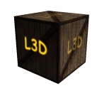
|
 |
 |
| Texture Unit 0 | Texture Unit 1 | Textured Cube |
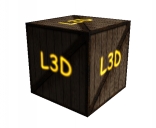
And now for something a little different: a glow in the dark effect. We want the second texture to glow in the dark, i.e. it will be fully bright when the light doesn't hit, and it will be dimmed as it gets more light.
|
|
| Additive Multi-Texture | Glowing Multi-Texture |
If intensity is zero then we want the second texture in its full strength. When the intensity is 1 we only want a 10% contribution of the second texture unit. For all the other values of intensity we want to interpolate. We can achieve this with the smoothstep function. This function has the following signature:
genType smoothStep(genType edge0, genType edge1, genType x);The result will be zero if x <= edge0, 1 if x >= edge1 and performs smooth Hermite interpolation between 0 and 1 when edge0 < x < edge1. In our case we want to call the function as follows:
coef = smoothStep(1.0, 0.2, intensity);The following fragment shader does the trick:
varying vec3 lightDir,normal;
uniform sampler2D tex,l3d;

void main()
{
	vec3 ct,cf,c;
	vec4 texel;
	float intensity,at,af,a;

	intensity = max(dot(lightDir,normalize(normal)),0.0);

	cf = intensity * (gl_FrontMaterial.diffuse).rgb +
					  gl_FrontMaterial.ambient.rgb;
	af = gl_FrontMaterial.diffuse.a;

	texel = texture2D(tex,gl_TexCoord[0].st);

	ct = texel.rgb;
	at = texel.a;

	c = cf * ct;
	a = af * at;

	float coef = smoothstep(1.0,0.2,intensity);
	c += coef *  vec3(texture2D(l3d,gl_TexCoord[0].st));

	gl_FragColor = vec4(c, a);
}
A Shader Designer project is available in here.
Many computations are done in eye space. This has to do with the fact that lighting needs to be performed in this space, otherwise eye position dependent effects, such as specular lights would be harder to implement.
Hence we need a way to transform the normal into eye space. To transform a vertex to eye space we can write:
vertexEyeSpace = gl_ModelViewMatrix * gl_Vertex;
So why can't we just do the same with a normal vector? First a normal is a vector of 3 floats and the modelview matrix is 4x4. This could be easily overcome with the following code:
normalEyeSpace = vec3(gl_ModelViewMatrix * vec4(gl_Normal,0.0));
So, gl_NormalMatrix is just a shortcut to simplify code writing? No, not really. The above line of code will work in some circunstances but not all.
Lets have a look at a potential problem:
In the above figure the modelview matrix was applied to all the vertices as well as to the normal and the result is clearly wrong: the normal is no longer perpendicular to the surface.
So now we know that we can't apply the modelview in all cases to transform the normal vector. The question is then, what matrix should we apply?
We know that, prior to the matrix transformation T.N = 0, since the vectors are by definition perpendicular. We also know that after the transformation N'.T' must remain equal to zero, since they must remain perpendicular to each other. Let's assume that the matrix G is the correct matrix to transform the normal vector. T can be multiplied safely by the upper left 3x3 submatrix of the modelview (T is a vector, hence the w component is zero). This is because T can be computed as the difference between two vertices, therefore the same matrix that is used to transform the vertices can be used to transform T. Hence the following equation:
The dot product can be transformed into a product of vectors, therefore:
Note that the transpose of the first vector must be considered since this is required to multiply the vectors. We also know that the transpose of a multiplication is the multiplication of the transposes, hence:
We started by stating that the dot product between N and T was zero, so if the following equation is true then we are on the right track.
Applying a little algebra yieds
Therefore the correct matrix to transform the normal is the transpose of the inverse of the M matrix. OpenGL computes this for us in the gl_NormalMatrix.
In the beginning of this section it was stated that using the modelview matrix would work in some cases. Whenever the 3x3 upper left submatrix of the modelview is orthogonal we have:
This is because with an orthogonal matrix, the transpose is the same as the inverse. So what is an orthogonal matrix? An orthogonal matrix is a matrix where all columns/rows are unit length, and are mutually perpendicular. This implies that when two vectors are multiplied by such a matrix, the angle between them after transformation by an orthogonal matrix is the same as prior to that transformation. Simply put the transformation preserves the angle relation between vectors, hence normals remain perpendicular to tangents! Furthermore it preserves the length of the vectors as well.
So when can we be sure that M is orthogonal? When we limit our geometric operations to rotations and translations, i.e. when in the OpenGL application we only use glRotate and gl_Translate and not glScale. These operations guarantee that M is orthogonal. Note: gluLookAt also creates an orthogonal matrix!
The dot product is commonly used to compute the cosine of the angle between two vectors. As we know this will only hold if both vectors are normalized. This is why we use the normalization operation in many shaders. In here we will see when we can skip this step, and we must use it.
When a normal vector arrives at a vertex shader is common to normalize it
normal = normalize(gl_NormalMatrix * gl_Normal);
The multiplication by the gl_NormaMatrix transforms the incoming normal to eye-space. The normalization guarantees a unit length vector as required to compute the cosine with a dot product.
So can we avoid the normalization? We'll in some cases we can. If the gl_NormaMatrix is orthogonal then we know that the length of the incoming vector is preserved, i.e. the length of normal is equal to the length of gl_Normal. Therefore, if the normals from the OpenGL application are normalized, which is common, we can avoid the normalization in the shader.
In practice this means that if we use gluLookAt to set the camera, and then perform only rotations and translations on our models, we can skip the normalization of the normal vector in the shader. It also means that a directional light will have its direction already normalized.
Fragment Shader
In the fragment shader we often find ourselves normalizing a vector which was just normalized in the vertex shader. Do we really need to do this? Well, the answer is yes, in most cases we do.
Consider a triangle with three different per vertex normal vectors. The fragment shader receives an interpolated normal, based on the distance from the fragment to the three vertices. The problem is that the interpolated vector, although it has the right direction, it doesn't have unit length.
The following diagram shows why this is the case. The black lines represent the faces (in 2D), the normals at the vertices are represented in blue. The green vector represents an interpolated normal at the fragment (represented with a dot). All interpolated normals will lie the dotted line. As can be seen in the figure, the green vector is smaller than the blue vectors (which are unit length, at least that was my intention :) ).
There is however a case when normalization can be skipped in the fragment shader, as long as the vectors per vertex are normalized. This is when the vectors per vertex all share the same direction, i.e. they are equal. The interpolation of such vectors would yield exactly the same vertex as the per vertex vectors, hence normalized (we assumed that the vertex vectors were normlized).
A simple example is when one considers a directional light. The direction is constant for all fragments, so if the direction is previously normalized, we can skip the normalization step in the fragment shader.