Extensible 3D (X3D)
Part 1: Architecture and base components
27 NURBS component
The name of this component is "NURBS". This name shall be used when referring to this component in the COMPONENT statement (see 7.2.5.4 Component statement).
This subclause describes the Non-uniform Rational B-Spline (NURBS) component of this part of ISO/IEC 19775. Table 27.1 provides links to the major topics in this subclause.
Non-uniform Rational B-Splines (NURBS) provide a convenient and efficient manner to generate curved lines and surfaces which can be smooth at any viewing distance. Since these surfaces are generated parametrically, only a small amount of data need be provided for describing complex surfaces.
The characteristics of a NURBS surfaces and curves are defined according to the mathematical definitions for Non-Uniform Rational B-Spline geometry.
There are many construction techniques including:
For this standard, it is assumed that creation of such surfaces is only a construction step at authoring time and that the surface will be represented as a general NurbsSurface node for X3D run-time delivery.
Background information on NURBS and some implementation strategies are described in [NURBS].
NURBs require input to be specified using control points, weights, knots and the order. Each of these inputs are defined using separate fields of the appropriate data type.
The control points and the corresponding weight values are held in separate fields. This separation also allows independent animation of the controlPoint fields using a CoordinateInterpolator node.
All nodes that use NURBs principles use the same field names (or u/v variations on them for the surface case). Those field names shall be interpreted as follows:
order defines the order of curve. From a mathematical point of view, the curve is defined by a polynomial of the degree order−1. The value of order shall be greater than or equal to 2. An implementation may limit order to a certain number. If it does so, then a warning shall be generated and the surface not displayed. An implementation shall at least support orders 2,3 and 4. The number of control points shall be at least equal to the order of the curve. The order defines the number of adjacent control points that influence a given control point.
controlPoint defines the X3DCoordinateNode instance that provides the source of coordinates used to control the curve or surface. Depending on the weight value and the order, this piecewise linear curve is approximated by the resulting parametric curve. The number of control points shall be equal to or greater than the order. A closed B-Spline curve can be specified by repeating the limiting control points, specifying a periodic knot vector, and setting the closed field to TRUE. If the last control point is not identical to the first or there exists a non-unitary value of weight within (order-1) control points of the seam, the closed field is ignored.
A weight value that shall be greater than zero is assigned to each controlPoint. The ordering of the values is equivalent to the ordering of the control point values. The number of values shall be identical to the number of control points. If the length of the weight vector is 0, the default weight 1.0 is assumed for each control point, thus defining a non-Rational curve. If the number of weight values is less than the number of control points, all weight values shall be ignored and a value of 1.0 shall be used.
knots defines the knot vector. The number of knots shall be equal to the number of control points plus the order of the curve. The order shall be non-decreasing. Within the knot vector there may not be more than order−1 consecutive knots of equal value. If the length of a knot vector is 0 or not the exact number required (numcontrolPoint + order − 1), a default uniform knot vector is computed.
Because low-level real-time rendering systems currently can handle only planar triangles, a NURBS surface needs to be broken down (i.e., tessellated) into a set of triangles approximating the true surface.
Tessellation can be done in different coordinate spaces:
There are different methods to determine tessellation points on the surface:
This standard does not specify which method is used to tessellate the surface. However, the implementation shall render the NURBS such that the approximation produces a rendered image in which the edges of the tessellation can not be perceived.
NOTE: Tessellation in screen space requires the ability to pass already transformed vertices for rendering. This requires the application to already light the vertices (see 17 Lighting component) and pass the resulting color and specular RGB values for each vertex of a triangle.
To avoid cracks at the junction of two surfaces, tessellation values of a whole set of surfaces can be specified in a NurbsSet.
The trimming curve specifies a NURBS-curve that limits the NURBS surface in order to create NURBS surfaces that contain holes or have smooth boundaries. Trimming curves are curves in the parametric space of the surface.
A trimming region is defined by a set of closed trimming loops in the parameter space of a surface. When a loop is oriented counter-clockwise, the area within the loop is retained, and the part outside is discarded. When the loop is oriented clockwise, the area within the loop is discarded, and the rest is retained. Loops may be nested, but a nested loop must be oriented oppositely from the loop that contains it. The outermost loop must be oriented counter-clockwise. Clockwiseness is determined by viewing the parametric surface from the side defined by the cross-product between the u and v axes of the parametric space.
A trimming loop consists of a connected sequence of NURBS curves and piecewise linear curves. The last point of every curve in the sequence shall be the same as the first point of the next curve, and the last point of the last curve shall be the same as the first point of the first curve. Self intersecting curves are not allowed.
X3DNurbsControlCurveNode : X3DNode {
  MFVec2d  [in,out] controlPoint []   (-∞,∞)
  SFNode   [in,out] metadata     NULL [X3DMetadataObject]
}
This abstract node type is the base type for all node types that provide control curve information in 2D space.
The control points are defined in 2D coordinate space and interpreted according to the descendent node type as well as the user of this node instance.
X3DNurbsSurfaceGeometryNode : X3DParametricGeometryNode {
  SFNode   [in,out] controlPoint  []    [X3DCoordinateNode]
  SFNode   [in,out] metadata      NULL  [X3DMetadataObject]
  SFNode   [in,out] texCoord      []    [X3DTextureCoordinateNode|NurbsTextureCoordinate]
  SFInt32  [in,out] uTessellation 0     (-∞,∞)
  SFInt32  [in,out] vTessellation 0     (-∞,∞)
  MFDouble [in,out] weight        []    (0,∞)
  SFBool   []       solid         TRUE
  SFBool   []       uClosed       FALSE
  SFInt32  []       uDimension    0     [0,∞)
  MFDouble []       uKnot         []    (-∞,∞)
  SFInt32  []       uOrder        3     [2,∞)
  SFBool   []       vClosed       FALSE
  SFInt32  []       vDimension    0     [0,∞)
  MFDouble []       vKnot         []    (-∞,∞)
  SFInt32  []       vOrder        3     [2,∞)
}
The X3DNurbsSurfaceGeometryNode represents the abstract geometry type for all types of NURBS surfaces.
uDimension and vDimension define the number of control points in the u and v dimensions.
uOrder and vOrder define the order of the surface in the u and v dimensions.
uKnot and vKnot define the knot values of the surface in the u and v dimensions.
uClosed and vClosed define whether or not the specific dimension is to be evaluated as a closed surface along the u and v directions, respectively.
controlPoint defines a set of control points of dimension uDimension × vDimension. This set of points defines a mesh where the points do not have a uniform spacing. uDimension points define a polyline in u-direction followed by further u-polylines with the v-parameter in ascending order. The number of control points shall be equal or greater than the order. A closed surface shall be specified by repeating the limiting control points and setting the closed field to TRUE. If the closed field is set to FALSE, the implementation shall not be required to smoothly blend the edges of the surface in that dimension into a continuous surface. A closed surface in either the u-dimension or the v-dimension shall be specified by repeating the limiting control points for that dimension and setting the respective uClosed or vClosed field to TRUE. If the last control point is not identical with the first control point, the field is ignored. If either the uClosed or the vClosed field is set to FALSE, the implementation shall not be required to smoothly blend the edges of the surface in that dimension into a continuous surface.
The control vertex corresponding to the control point P[i,j] on the control grid is:
    P[i,j].x = controlPoint[i + ( j × uDimension)].x
    P[i,j].y = controlPoint[i + ( j × uDimension)].y
    P[i,j].z = controlPoint[i + ( j × uDimension)].z
    P[i,j].w = weight[ i + (j × uDimension)]

    where 0 ≤ i < uDimension and
          0 ≤ j < vDimension.
For an implementation subdividing the surface in a equal number of subdivision steps, tessellation values could be interpreted in the following way:
For implementations doing tessellations based on chord length, tessellation values less than zero are interpreted as the maximum chord length deviation in pixels. Implementations doing fully automatic tessellation may ignore the tessellation hint parameters.
texCoord provides additional information on how to generate texture coordinates. By default, texture coordinates in the unit square (or cube for 3D coordinates) are generated automatically from the parametric subdivision. A NurbsTextureCoordinate node or simply a TextureCoordinate node can then be used to compute a texture coordinate given a u/v parameter of the NurbsSurface. The NurbsTextureCoordinate also supports non-animated surfaces to specify a "chord length"-based texture coordinate parametrization.
The solid field determines whether the surface is visible when viewed from the inside. 11.2.3 Common geometry fields provides a complete description of the solid field.
X3DParametricGeometryNode : X3DGeometryNode {
  SFNode [in,out] metadata NULL  [X3DMetadataObject]
}
This abstract node type is the base type for all geometry node types that are created parametrically and use control points to describe the final shape of the surface. How the control points are described and interpreted shall be a property of the individual node type.
Contour2D : X3DNode {
  MFNode [in]     addChildren         [NurbsCurve2D|ContourPolyline2D]
  MFNode [in]     removeChildren      [NurbsCurve2D|ContourPolyline2D]
  MFNode [in,out] children       []   [NurbsCurve2D|ContourPolyline2D]
  SFNode [in,out] metadata       NULL [X3DMetadataObject]
}
The Contour2D node groups a set of curve segments to a composite contour. The children shall form a closed loop with the first point of the first child repeated as the last point of the last child and the last point of a segment repeated as the first point of the consecutive one. The segments shall be defined by concrete nodes that implement the X3DNurbsControlCurveNode abstract type nodes and shall be enumerated in the child field in consecutive order according to the topology of the contour.
The 2D coordinates used by the node shall be interpreted to lie in the (u, v) coordinate space defined by the NURBS surface.
ContourPolyline2D : X3DNurbsControlCurveNode {
  SFNode  [in,out] metadata     NULL [X3DMetadataObject]
  MFVec2D [in,out] controlPoint []   (-∞, ∞)
}
The ContourPolyline2D node defines a piecewise linear curve segment as a part of a trimming contour in the u,v domain of a surface.
The controlPoint field specifies the end points of each segment of the piecewise linear curve.
ContourPolyline2D nodes are used as children of the Contour2D group.
CoordinateDouble : X3DCoordinateNode {
  SFNode  [in,out] metadata NULL [X3DMetadataObject]
  MFVec3d [in,out] point    []   (-∞,∞)
}
CoordinateDouble is a variant of the Coordinate node that allows the definition of 3D coordinates in double precision floating point values.
NurbsCurve : X3DParametricGeometryNode {
  SFNode   [in,out] controlPoint []    [X3DCoordinateNode]
  SFNode   [in,out] metadata     NULL  [X3DMetadataObject]
  SFInt32  [in,out] tessellation 0     (-∞,∞)
  MFDouble [in,out] weight       []    (0,∞)
  SFBoolean[]       closed       FALSE
  MFDouble []       knot         []    (-∞,∞)
  SFInt32  []       order        3     [2,∞)
}
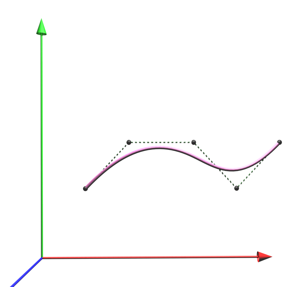
The NurbsCurve node is a geometry node defining a parametric curve in 3D space (see Figure 27.1)
The tessellation field gives a hint to the curve tessellator by setting an absolute number of subdivision steps. These values shall be greater than or equal to the Order field. A value of 0 indicates that the browser choose a suitable tessellation. Interpretation of values below 0 is implementation dependent.
For an implementation subdividing the surface into an equal number of subdivision steps, tessellation values are interpreted as follows:
For implementations doing tessellations based on chord length, tessellation values less than zero are interpreted as the maximum chord length deviation in pixels. Implementations doing fully automatic tessellation may ignore the tessellation hint parameters.
Figure 27.1 — NurbsCurve
NurbsCurve2D : X3DNurbsControlCurveNode {
  MFVec2d  [in,out] controlPoint []    (-∞,∞)
  SFNode   [in,out] metadata     NULL  [X3DMetadataObject]
  SFInt32  [in,out] tessellation 0     (-∞,∞)
  MFDouble [in,out] weight       []    (0,∞)
  MFDouble []       knot         []    (-∞,∞)
  SFInt32  []       order        3     [2,∞)
  SFBool   []       closed       FALSE
}
The NurbsCurve2D node defines a trimming segment that is part of a trimming contour in the u,v domain of the surface.
NurbsCurve2D nodes are used as children of the Contour2D group.
NurbsOrientationInterpolator : X3DChildNode {
  SFFloat    [in]     set_fraction       (-∞,∞)
  SFNode     [in,out] controlPoint []   [X3DCoordinateNode]
  MFDouble   [in,out] knot          []   (-∞,∞)
  SFNode     [in,out] metadata      NULL [X3DMetadataObject]
  SFInt32    [in,out] order         3    (2,∞)
  MFDouble   [in,out] weight        []   (-∞,∞)
  SFRotation [out]    value_changed
}
NurbsOrientationInterpolator specifies a 3D NURBS Curve using the same fields as described for the NurbsCurve node.
The field set_fraction has the same meaning as in the NurbsPositionInterpolator.
Sending a set_fraction input computes a 3D position on the curve, from which a tangent to the curve at that position is calculated. The tangent direction shall be oriented to point along the curve from the first knot value towards the last value. This orientation value shall be then sent by value_changed. Given the same definition for control points, knots, order and weights, and the same value for set_fraction the orientation interpolator shall generate the orientation of the tangent of the curve at the same position as the NurbsPositionInterpolator.
NurbsPatchSurface : X3DNurbsSurfaceGeometryNode {
  SFNode   [in,out] controlPoint  []    [X3DCoordinateNode]
  SFNode   [in,out] metadata      NULL  [X3DMetadataObject]
  SFNode   [in,out] texCoord      []    [X3DTextureCoordinateNode|NurbsTextureCoordinate]
  SFInt32  [in,out] uTessellation 0     (-∞,∞)
  SFInt32  [in,out] vTessellation 0     (-∞,∞)
  MFDouble [in,out] weight        []    (0,∞)
  SFBool   []       solid         TRUE
  SFBool   []       uClosed       FALSE
  SFInt32  []       uDimension    0     [0,∞)
  MFDouble []       uKnot         []    (-∞,∞)
  SFInt32  []       uOrder        3     [2,∞)
  SFBool   []       vClosed       FALSE
  SFInt32  []       vDimension    0     [0,∞)
  MFDouble []       vKnot         []    (-∞,∞)
  SFInt32  []       vOrder        3     [2,∞)
}
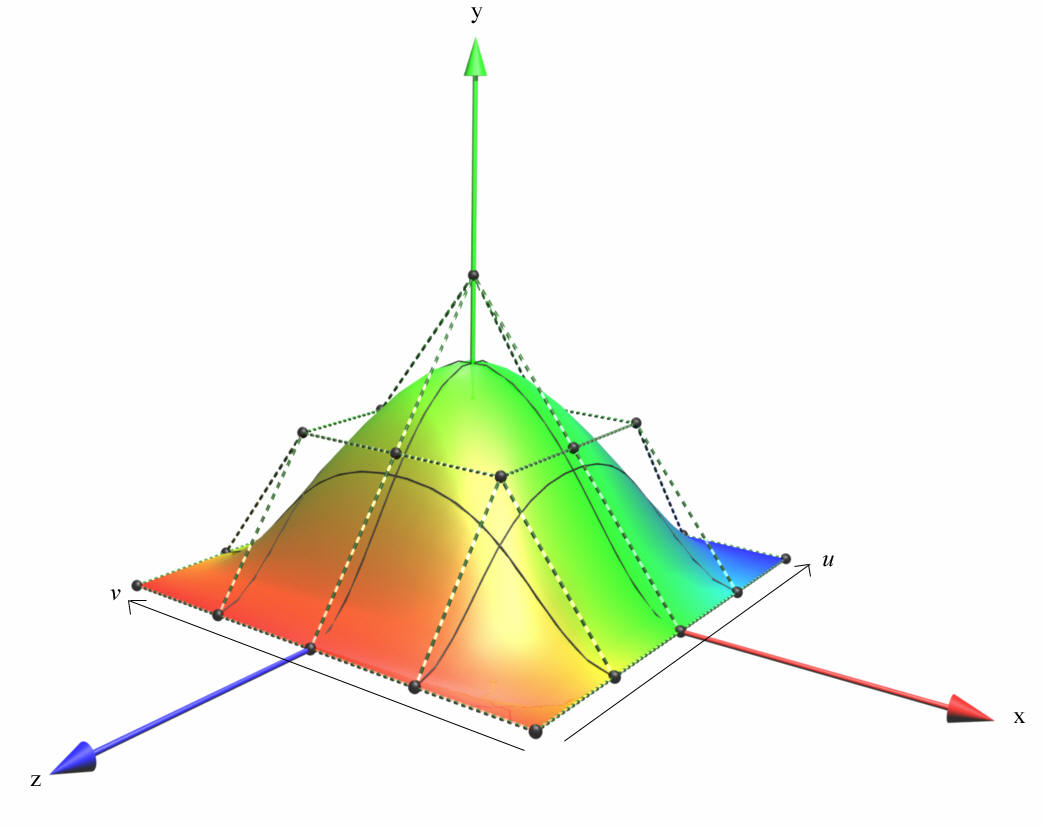
The NurbsPatchSurface node is a contiguous NURBS surface patch. Figure 27.2 shows an example of a NurbsPatchSurface node:
Figure 27.2 — NurbsPatchSurface
NurbsPositionInterpolator : X3DChildNode {
  SFFloat  [in]     set_fraction        (-∞,∞)
  SFNode   [in,out] controlPoint []   [X3DCoordinateNode]
  MFDouble [in,out] knot          []   (-∞,∞)
  SFNode   [in,out] metadata      NULL [X3DMetadataObject]
  SFInt32  [in,out] order         3    (2,∞)
  MFDouble [in,out] weight        []   (-∞,∞)
  SFVec3f  [out]    value_changed
}
NurbsPositionInterpolator describes a 3D NURBS Curve using dimension, keyValue, keyWeight, knot, and order as specified in 27.4.4 NurbsCurve.
The fields set_fraction and value_changed have the same meaning as specified in 19.4.6 PositionInterpolator.
Sending a set_fraction input computes a 3D position on the curve, which is sent by value_changed. The set_fraction value is used as the input value for the tessellation function. Thereby, the knot corresponds to the key field of a conventional interpolator node; i.e., if the set_fraction value is within [0,1] and the knot vector within [0,2], only half of the curve is computed.
NurbsSet : X3DChildNode, X3DBoundedObject {
  MFNode  [in]     addGeometry                [NurbsSurface]
  MFNode  [in]     removeGeometry             [NurbsSurface]
  MFNode  [in,out] geometry          []       [NurbsSurface]
  SFNode  [in,out] metadata          NULL     [X3DMetadataObject]
  SFFloat [in,out] tessellationScale 1.0      (0,∞)
  SFVec3f []       bboxCenter        0 0 0    (-∞,∞)
  SFVec3f []       bboxSize          -1 -1 -1 [0,∞) or −1 −1 −1
}
The NurbsSet node groups a set of NurbsSurface nodes to a common group for rendering purposes only. This provides informs the browser that the set of NurbsSurfaces shall be treated as a unit during tessellation to enforce tessellation continuity along borders. The tessellationScale parameter is scaling the tessellation values in lower level NurbsSurface nodes. A set of NurbsSurfaces that use a matching set of controlPoint along the borders shall result in a common tessellation stepping.
The geometry represented in the children of this node shall not be directly rendered. It is an informational node only. Surfaces not represented elsewhere in the transformation hierarchy shall not be rendered.
The bounds information is provided for optimization purposes only. A browser may choose to use this information about when to apply trimming or smooth tessellation between patches based on the bounds information (EXAMPLE only smooth when the viewer is within the bounds).
NurbsSurfaceInterpolator : X3DChildNode {
  SFVec2f  [in]     set_fraction          (-∞,∞)
  SFNode   [in,out] controlPoint    []   [X3DCoordinateNode]
  SFNode   [in,out] metadata         NULL [X3DMetadataObject]
  MFDouble [in,out] weight           []   (-∞,∞)
  SFVec3f  [out]    position_changed
  SFVec3f  [out]    normal_changed
  SFInt32  []       uDimension       0    [0,∞)
  MFDouble []       uKnot            []   (-∞,∞)
  SFInt32  []       uOrder           3    [2,∞)
  SFInt32  []       vDimension       0    [0,∞)
  MFDouble []       vKnot            []   (-∞,∞)
  SFInt32  []       vOrder           3    [2,∞)
}
NurbsSurfaceInterpolator describes a 3D NURBS surface as specified in 27.4.7 NurbsPatchSurface.
Sending a set_fraction input computes a 3D position on the surface for the given u and v coordinates, from which the position in the surface shall be then sent by value_changed.
NurbsSweptSurface : X3DParametricGeometryNode {
  SFNode [in,out] crossSectionCurve []   [X3DNurbsControlCurveNode]
  SFNode [in,out] metadata          NULL [X3DMetadataObject]
  SFNode [in,out] trajectoryCurve   []   [NurbsCurve]
  SFBool []       ccw               TRUE
  SFBool []       solid             TRUE
}
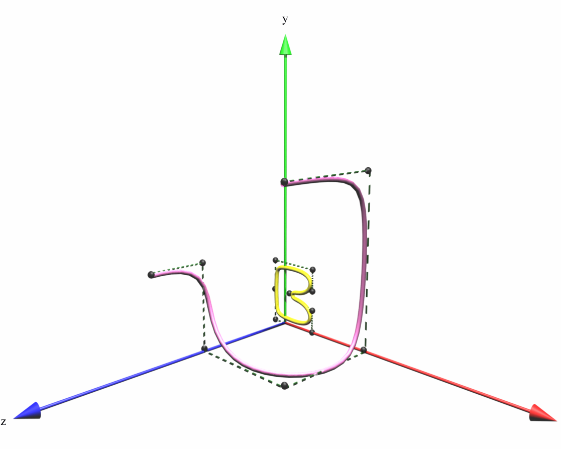
NurbsSweptSurface describes a generalized surface that defines a path in 2D space and constant cross section that may be 2D or 3D of the path as illustrated in Figure 27.3. Conceptually it is the NURBS equivalent of the Extrusion node (see 13.3.5 Extrusion) but permits the use of non-closed cross sections.
Figure 27.3 — NurbsSweptSurface
The solid and ccw fields are defined as specified in 11.2.3 Common geometry fields. To have the polygons' normals facing away from the axis, the trajectory curve should be oriented so that it is moving counterclockwise when looking down the −Y axis, thus defining a concept of "inside" and "outside".
With solid TRUE and ccw TRUE, the cylinder is visible from the outside. Changing ccw to FALSE makes it visible from the inside.
NurbsSwungSurface : X3DParametricGeometryNode {
  SFNode [in,out] metadata          NULL [X3DMetadataObject]
  SFNode [in,out] profileCurve      []   [X3DNurbsControlCurveNode]
  SFNode [in,out] trajectoryCurve   []   [X3DNurbsControlCurveNode]
  SFBool []       ccw               TRUE
  SFBool []       solid             TRUE
}
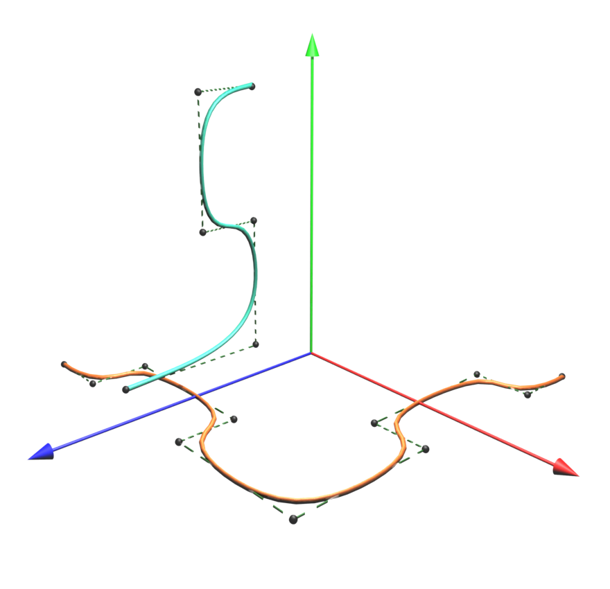
NurbsSwungSurface describes a generalized surface that defines a path and constant cross section of the path as illustrated in Figure 27.4.
Figure 27.4 — NurbsSwungSurface
The profile curve is a 2D curve in the yz-plane that describes the cross-sectional shape of the object.
The trajectory curve is a 2d curve in the xz-plane that describes the path over which to trace the cross-section.
The solid and ccw fields are defined in 11.2.3 Common geometry fields. To have the normals of the polygons facing away from the axis, the trajectory curve should be oriented so that it is moving counterclockwise when looking down the −Y axis, thus defining a concept of "inside" and "outside".
With solid TRUE and ccw TRUE, the cylinder is visible from the outside. Changing ccw to FALSE specifies that the cylinder is visible from the inside.
NurbsTextureCoordinate : X3DNode {
  MFVec2f  [in,out] controlPoint []   (-∞,∞)
  SFNode   [in,out] metadata     NULL [X3DMetadataObject]
  MFFloat  [in,out] weight       []   (0,∞)
  SFInt32  []       uDimension   0    [0,∞)
  MFDouble []       uKnot        []   (-∞,∞)
  SFInt32  []       uOrder       3    [2,∞)
  SFInt32  []       vDimension   0    [0,∞)
  MFDouble []       vKnot        []   (-∞,∞)
  SFInt32  []       vOrder       3    [2,∞)
}
The NurbsTextureCoordinate node is a NURBS surface existing in the parametric domain of its surface host specifying the mapping of the texture onto the surface.
The parameters are as specified in X3DNurbsSurfaceGeometryNode with the exception that the control points are specified in (u, v) coordinates.
The tessellation process generates 2D texture coordinates. If a NurbsTextureCoordinate is undefined, texture coordinates are computed by the client on the basis of parametric step size. Conventional vertex parameters do not apply on NURBS surfaces because triangles are only available after polygonalization. However, the conventional texture transform may be used.
NurbsTextureCoordinate nodes are accessed through the texCoord field of a node derived from X3DNurbsSurfaceGeometryNode. A NurbsTextureCoordinate node separately encountered is ignored.
NurbsTrimmedSurface : X3DNurbsSurfaceGeometryNode {
  MFNode   [in]     addTrimmingContour          [Contour2D]
  MFNode   [in]     removeTrimmingContour       [Contour2D]
  SFNode   [in,out] controlPoint          []    [X3DCoordinateNode]
  SFNode   [in,out] metadata              NULL  [X3DMetadataObject]
  SFNode   [in,out] texCoord              []    [X3DTextureCoordinateNode|NurbsTextureCoordinate]
  MFNode   [in,out] trimmingContour       []    [Contour2D]
  SFInt32  [in,out] uTessellation         0     (-∞,∞)
  SFInt32  [in,out] vTessellation         0     (-∞,∞)
  MFDouble [in,out] weight                []    (0,∞)
  SFBool   []       solid                 TRUE
  SFBool   []       uClosed               FALSE
  SFInt32  []       uDimension            0     [0,∞)
  MFDouble []       uKnot                 []    (-∞,∞)
  SFInt32  []       uOrder                3     [2,∞)
  SFBool   []       vClosed               FALSE
  SFInt32  []       vDimension            0     [0,∞)
  MFDouble []       vKnot                 []    (-∞,∞)
  SFInt32  []       vOrder                3     [2,∞)
}
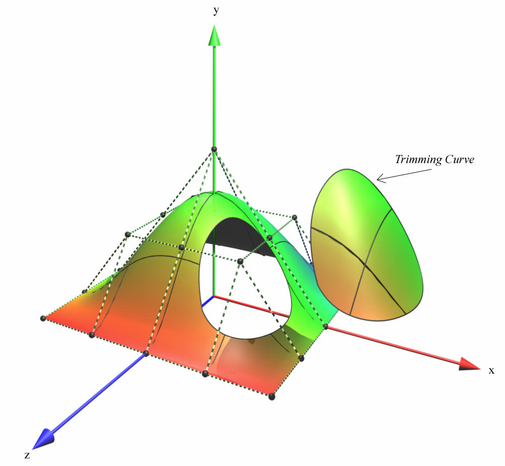
The NurbsTrimmedSurface node defines a NURBS surface (see 27.4.7 NurbsPatchSurface) that is trimmed by a set of trimming loops. The outermost trimming loop shall be defined in a counterclockwise direction. An example of a NurbsTrimmedSurface node is shown in Figure 27.5.
Figure 27.4 — NurbsTrimmedSurface
The trimmingContour field, if specified, shall contain a set of Contour2D (see 27.4.1 Contour2D) nodes. Trimming loops shall be processed as described for the Contour2D node. If no trimming contours are defined, The NurbsTrimmedSurface node shall have the same semantics as the NurbsPatchSurface node.
The Non-uniform Rational B-spline (NURBS) component provides four levels of support as specified in Table 27.2. Level 1 provides basic NURBS support. Level 2 adds the ability to ensure controlled tessellation along the boundaries between two NURBS surfaces. Level 3 adds specialized NURBS nodes. Level 4 adds trimmed NURBS surfaces.
Table 27.2 — NURBS component support levels
| Level | Prerequisites | Nodes/Features | Support |
|---|---|---|---|
| 1 | Core 1 Grouping 1 Shape 1 Interpolator 1 Texturing 1 |
||
| X3DNurbsControlCurveNode (abstract) | Full support | ||
| X3DNurbsSurfaceGeometryNode (abstract) | Full support | ||
| X3DParametricGeometryNode (abstract) | Full support | ||
| CoordinateDouble | All fields fully supported | ||
| NurbsCurve | All fields fully supported | ||
| NurbsOrientationInterpolator | All fields fully supported | ||
| NurbsPatchSurface | All fields fully supported | ||
| NurbsPositionInterpolator | All fields fully supported | ||
| NurbsSurfaceInterpolator | All fields fully supported | ||
| NurbsTextureCoordinate | All fields fully supported | ||
| 2 | Core 1 Grouping 1 Shape 1 Interpolator 1 Texturing 1 |
||
| All Level 1 NURBS nodes | As supported in Level 1 | ||
| NurbsSet | All fields fully supported | ||
| 3 | Core 1 Grouping 1 Shape 1 Interpolator 1 Texturing 1 |
||
| All Level 2 NURBS nodes | As supported in Level 2 | ||
| NurbsCurve2D | All fields fully supported | ||
| ContourPolyline2D | All fields fully supported | ||
| NurbsSweptSurface | All fields fully supported | ||
| NurbsSwungSurface | All fields fully supported | ||
| 4 | Core 1 Grouping 1 Shape 1 Interpolator 1 Texturing 1 |
||
| All Level 3 NURBS nodes | As supported in Level 3 | ||
| Contour2D | All fields fully supported | ||
| NurbsTrimmedSurface | All fields fully supported |